The Force Density Method - A Brief Introduction
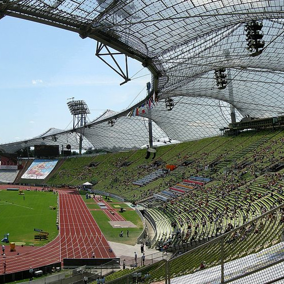
The method of force density was developed in response to the need for computational modelling of structures for the Munich Olympic complex [Lewis 2013] . The method relies on the assumption that the ratio of tension force to length of each cable can be constant, transforming a system of non-linear equations to a set of linear equations which can be solved directly.
The Force Density Method (FDM), first introduced by Scheck [1974], is commonly used in engineering to find the equilibrium shape of a structure consisting of a network of cables with different elasticity properties when stress is applied. While shape analysis of tensile structures is a geometrically non-linear problem, the FDM linearises the form-fitting equations analytically by using the force density ratio for each cable element, \(q = F/L\), where \(F\) and \(L\) are the force and length of a cable element respectively.
The Force Density Method
Given the positions of nodes (vertices) which connect the cables (edges) of our network \(V\), the topology of this network is encoded in the branch-node matrix \(C\). The branch-node matrix of the network above is given by:
 Given a load vector \(R\) and the diagonal matrix of force densities \(Q\), the equilibrium location can be deduced by solving for \(X\) in
$$(C^T Q C) X = R.$$
Embedding
In order to use the FDM for 2D embedding, we must be able to constrain nodes on the boundary. For this, the matrix \(C\) is separated into two sub–matrices: \(C_f\) contains constrained nodes with corresponding position \(X_f\), while \(C\) contains those that are free to move. The problem is reformulated as $$(C^T Q C) X = R - (C^T Q C_f)X_f.$$
Note that for the purposes of embedding, \(R\) is typically set to zero.
The FDM is fold-over free. This is explained with reference to the following Figure:

Stability under motion
The FDM cannot guarantee any of the commonly advocated properties of embeddings in computer graphics, such as isometry (length preserving) or conformality (angle preserving). In our application, it is desirable that the path of a vertex or a group of vertices moving across the surface of the shape is mirrored in the embedding. We evaluate this phenomenon by measuring the distortion of these displacement vectors in the embedded space. We call this property stability under motion.

 |  |  |
In the above Figure we compare two popular fixed boundary conformal techniques, Harmonic mappings [Eck at al. 1995] and Mean Value Coordinates [Floater 2003] with an FDM network constructed with unit edge forces. The stability under motion of these embedding methods is highly non-linear, and so we evaluate each embedding technique experimentally as follows:
- Compute the embedding \(\mathcal{U}_0 = \mathsf{embed}\left(\mathcal{M}_0\right)\).
- Rotate a set of points on the sphere (in this case, one triangle) in a straight path around the surface of the sphere.
- For each state of the rotation \(\mathcal{M}_i\) compute \(\mathcal{U}_i=\mathsf{embed}\left(\mathcal{M}_i\right)\).
- Compute the \(n\) displacement vectors in the embedded space. For each \(u_{0,i} \in \mathcal{U}_O\) and \(u_{d,i} \in \mathcal{U}_d\) define \(\mathbf{d}_i\) as the vector between \(u_{0,i}\) and \(u_{d,i}\). Let \( D = \left[\mathbf{d}_1, \ldots , \mathbf{d}_n\right]^T \).
- We use the angle of the normal cone of these displacement vectors $$\alpha = \max_{i,j} \left(\mathrm{acos}(\mathbf{d}_i \cdot \mathbf{d}_j)\right)$$ as the distortion error. For this experiment, we evaluate the distortion of only the points moving on the surface.
We demonstrated that under all rotations the FDM embedding is stable, even when faces of \(\mathcal{M}_d\) overlap. In addition, there is considerably less displacement of surrounding nodes after rotations.
Conclusion
I have presented the force density method as a technique to perform mesh embedding using this technique. It is computationally efficient, as it only involves the solution to a sparse linear system, easily solved with the Conjugate Gradient Method or using Cholesky Factorization. I demonstrated that embedding with FDM is very stable, preventing foldover and discontinuities when parameterizing an unstable triangulation. This is particularly useful when, for example, you need to flatten geometry in a stable fashion (for example, see Zhang et al. [2007] and our paper on skin sliding).
Bibliography
Matthias Eck, Tony DeRose, Tom Duchamp, Hugues Hoppe, Michael Lounsbery, and Werner Stuetzle. Multiresolution analysis of arbitrary meshes. ACM Transactions on Graphics (Proceedings of SIGGRAPH ‘95). 173-182 doi: 10.1145/218380.218440.
Michael S. Floater, Mean value coordinates, Computer Aided Geometric Design, 20(1):19-27, 2003, ISSN 0167-8396, 10.1016/S0167-8396(03)00002-5.
Wanda J. Lewis. Tension Structures: Form and Behaviour. Thomas Telford, illustrated edition, 2003. ISBN 0727732366, 9780727732361.
J. H. Schek. The force density method for form finding and computation of general networks. Computer Methods in Applied Mechanics and Engineering, (3):115–134, 1974. doi: 10.1016/0045-7825(74)90045-0
Zhang, J. J., Yang, X. and Zhao, Y. (2007), Bar-net driven skinning for character animation. Comp. Anim. Virtual Worlds, 18: 437–446. doi: 10.1002/cav.211
Richard Southern
Head of Department
National Centre for Computer Animation
Researcher and Lecturer in Computer Graphics